I spent lots of time and effort between January 2014 and the end of July 2014 doing body work and painting the GMC. While I was preparing for the trip to the Fall 2014 GMC Western States Motorhome Club rally in Manteca, CA I was asked to do a seminar at the rally. Preparing the seminar I did the following write-up first and then made the slide presentation from it. The slide presentation is available at the bottom of this post.
Color selection and design:
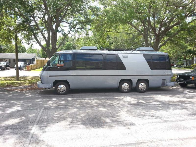
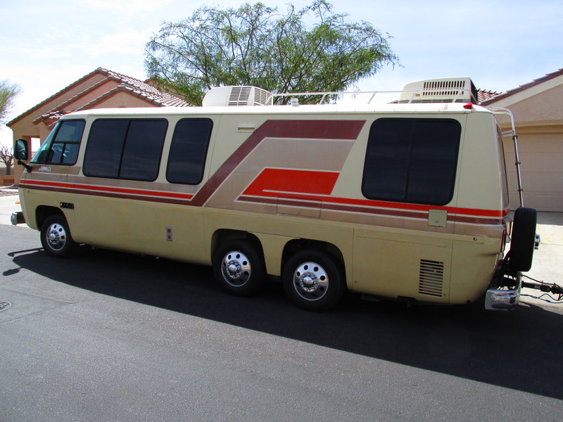
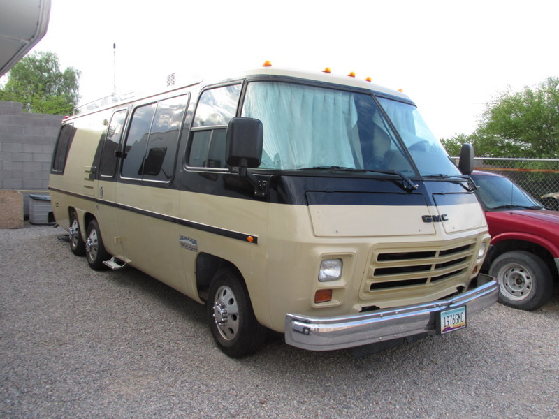
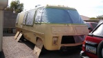
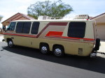
 We have had our Classic GMC Motorhome for almost 8 years and for all of that time a paint job was very high on our list of desired improvements. We tried buffing the original Imron paint but there had been repairs that were not Imron. The stripes were painted on top of the Imron and were well worn in addition to being very 1970s – the orange stripe was the biggest clue for dating it.
 We made many improvements: mechanical, convenience and cosmetic. In 2010 we remodeled the entire interior – all new cabinets and window coverings but we never got around to the paint job. In 2014, the paint job finally made its way to the top of the “desired improvements” list so it was time to do something about it.
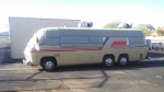
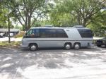 Over the eight years and multiple rallies at both GMC Motorhomes International and GMC Western States, along with lots of photos from rallies we could not attend we developed an idea of what we wanted for a paint design. The dream paint-job was based on a design that I saw on Jim Bounds’ web site – he calls the coach Blueocity. Blueocity’s base color is a bluish gray with black around the windows. Our dream job had a base color of beige (no specific shade but) close or similar to the original base color to keep it light and compatible with our interior colors.
When I went out looking for a shop that would do the job (more on that below) I was told that changing the design from the original would cost quite a bit more because of all of the sanding required to hide the old stripes. Rethinking the design, we came up with the possibility of repainting the same design with new colors. At that point I contacted Byron Songer, the design and graphic arts guru. Before Byron did anything, however, we changed our minds (I decided to do the paint job myself – more below again) and went back to our original plan.
When I finally went to the paint supplier I found out about a complicating factor that might have forced us to abandon any Byron Songer solution anyway: automotive paint colors are “a crap shoot”. It turns out that available automotive paint colors, for the most part, are determined by automotive manufacturers. The color choosing process is to look at thick books of paint colors with small (about 1” square) swatches of available paint colors in no obvious order – they seem to be in order by manufacturer and model year. There are no meaningful color names, only numbers, and no available range of a color as there is in home décor type paint store. This would make painting the original colors easy but not great for design.
Hire someone or do it myself?:
My original plan was to find someone to do the paint job for me but I ended up doing it myself. I had toyed with the idea of painting the coach myself because it was interesting – I love learning how to do things. Also, I knew two people who had done it themselves in their driveways and both coaches looked fine – no evidence that they were done by amateurs.
Trying to find someone, I researched and thought about the tried and true Jim Bounds Coop in Orlando, FL and Topeka Graphics in Indiana. I knew (Steve Ferguson and Jim Decheine) that Jim Bounds did great (the best) work but I had heard that the price was quite high – $10K – $12K plus the trip to Florida (leaving it there would require two trips adding quite a bit to the already high cost). I thought of Topeka Graphics because they had done several GMCs for others and the quality was good and the price seemed right at the time – about $5K. When I called them about a year ahead of time they had stopped painting coaches and gone back to their prime work of doing graphics on big RVs.
Now I started searching around the Tucson and Phoenix areas. I called shops which seemed to be likely to be able to do the job but was unable to find anyone who would do it. I asked people who had coaches painted and only two shops were identified. One of the people who stores their non-GMC RV where I do had theirs done at a shop in Tucson. When I visited the shop and showed them the coach they were very negative and, although cheap, were going to do a bare-minimum job if they did it at all. Also, they did not have a facility so would have to do it outside.
I ran into the owner of a very large diesel pusher at a Jetset rally who had just had his coach painted at a place in Tucson that does RVs for one of the local dealers. He had paid only about $8,000 and it was huge so I went to see them. They had the facilities and the knowledge but, if I did much of the grunt work (removing and reinstalling all of the lights, etc.) and gave them the coach for at least 2 months, they would (no body work since I had already done most of it) paint the coach for only $9,000. That is when I realized that Jim Bounds’ price was pretty fair and also when I decided to do it myself. I figured that if I could finish with a “10-foot” paint job I would be happy and would equal some of the paint jobs I have seen done in “Mexico” or elsewhere (cheap). A “10-foot” paint job means: from 10 feet away it looks great.
What was required to do it myself?
Skill requirements:
Doing the paint job myself seemed like an exciting and rewarding project. I had sprayed paint before when I made cabinets and furniture and I knew others (Steve A., Karen B., and Sully) who had painted their own coaches themselves at home, in the driveway. If they could, so could I.
It turned out that there are hundreds of free videos on youtube.com that teach everything you need to know about body work and painting. I watched many hours of video trying to learn what I needed to do the job.
Youtube:
- DIY How To Paint A Car School
- diyautoschool
- Eastwood Company (Kevin’s Corner with Kevin Tetz)
- Official How To Paint A Car – DIY Learn Auto Body And Paint
- Refinish Network
Tool requirements:
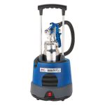 The biggest hitch seemed to be an air compressor to run the spray gun and the sanders. I had a small air compressor but everything I read talked about how you need a lot of air and the only way to get the amount they suggested was to use a huge 220-volt air compressor that would cost at least $500 but more like $1000 or more. Well, the truth turns out to be that the reason body shops use spray guns that require lots of air is that they have lots of air. Body shops have air tools like sanders, chisels, hammers, etc. that have always taken lots of air. HVLP spray guns – the state of the art tools – do not require pressure, just lots of volume. HVLP guns, as originally developed, are driven by turbines that move lots of air at low pressures – like the exhaust side of a vacuum cleaner.
Turbine system Benefits:
1) Complete Portability typically 20 lbs.
2) Built in filter system
3) All Self contained
4) Fast operation with heated material (I needed something to slow it down)
4) Excellent finish quality
5) Very Low Overspray – Great for indoor applications
6) No moisture to worry about
Other electric or air tools required: 4 ½” angle grinder/sander for body work, a 5” random orbit sander, and a 1/4-sheet finishing sander from Makita (easy to use and very aggressive).
Where to work?
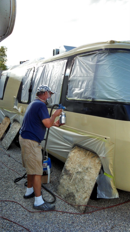
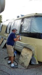
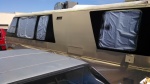
 I am not allowed to park the GMC at my house so either renting a space somewhere, indoors or out, or doing it right where it was stored were my only options. There were no opportunities I could find for renting space indoors so I decided, with the approval of the storage lot owner, to paint the coach right where it was parked. There were two fairly trashed cars on one side that belonged to Ed, the storage lot owner and a white class C Motorhome on the other. There was less than 8 feet between each of the spaces so overspray was a big concern for me.
The turbine-based HVLP spray system turned out to be a life-saver again. The first section I painted was below the waist on the side nearest the cars and there was almost no overspray. I had planned to turn the coach around so that I was painting on the car side again – Ed “didn’t care” about the cars’ paint jobs – but I decided that there was no risk just leaving it right where it was. The only time I did move the coach was when I painted the roof. I worried about paint going over the top and onto the Motorhome on the other side so I moved out into an open parking lot in the storage facility.
 Speaking of painting the roof: how to reach it was the biggest problem I had with the work area. I don’t know how real shops paint the roofs of GMCs. I think I remember even Jim Bounds saying that they send coaches out somewhere to have the roofs painted. I did see a situation where someone painted theirs in a barn where they could walk on platforms or planks suspended above the vehicle. I ended up using an 8-foot stepladder leaning on the side of the coach and had to move it 3 or 4 feet at a time but reaching the front was a real problem that I might do differently next time – if I could think of anything that I couldn’t this time.
Other than some dust and a few bugs in the finished paint job painting the coach out in the weather on a gravel lot in the Arizona Summer sun worked out OK. I did all of the painting as early as there was light enough to start – usually 5:00 to 5:30 a.m.
Painting the coach
Preparation:
There are basically two ways to paint a vehicle: “bag and shoot” or “the right way”. Jim Bounds and the GMC Coop in Orlando, FL is the “gold standard” for painting the GMC. “Bag and shoot” is what Jim calls the typical cheap paint job. Everything that can be masked is masked, little or nothing that is not to be painted is removed. The right way to paint a vehicle is to remove everything that can be removed so that nothing gets painted that shouldn’t be and so that the surrounding areas can be properly cleaned and prepped. Another benefit is that when the item is removed and replaced there is no problem with a change in shape and old paint showing as a result.
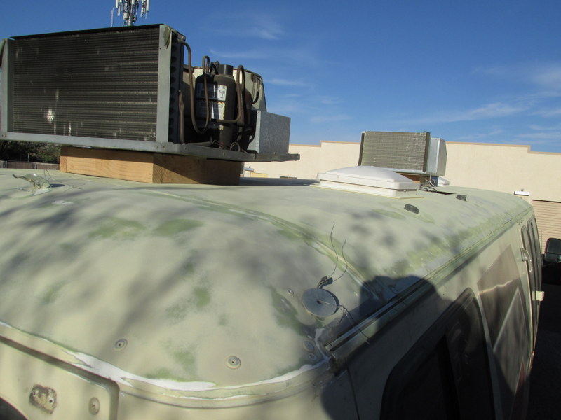
 I took the path of removing everything. The only things that I did not remove are the vent fans on the roof but I did remove the caulking and clean the areas around them. The air conditioners – two of them – were too heavy for me to completely remove so I built 14-inch by 14-inch frames out of 2x4s on their edges. The frames move the base of the A/C unit 3 ½ inches above the roof – enough to get paint underneath and do the job.
One of the biggest questions that I had and I see others discussing on the web was whether or not to remove the drip rails (the rain gutters that cover the seams between the roof and the sides). I asked Jim about this and he told me that they always do and that, although it is a big job, it was the “correct” thing to do – I removed mine and I am glad I did. One rail, on the passenger side, came off with no problems – probably because someone had been their before me some years earlier. The driver’s side was a different story. About every other screw broke off in the structural rib. Jim had predicted this and said just move it forward about ¼” and drill all new holes when reinstalling.
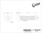 The replacement of the driver’s side rail required me to grind the old broken screws down flush with the aluminum. I used a 4 ½” grinder with a metal cutting wheel on it to reach into the groove where the screws go in. I bought some self-tapping screws from McMaster-Carr and used a slightly oversized drill bit (11/64) for drilling the new holes and I had no problems getting the new screws in and tight.
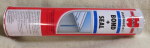
| I used 11/64″ drill bits, specifically: DEWALT DW1211 11/64-Inch Cobalt Split Point Twist Drill Bit. |
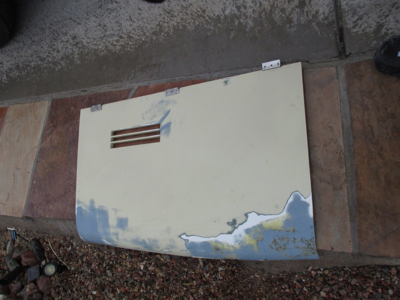
I did remove the front “hood” doors and the fuel, hookup, and water-fill doors for sanding and repair but I reinstalled them before painting so that the hinges, rivets and screws would be painted.
Body Work:
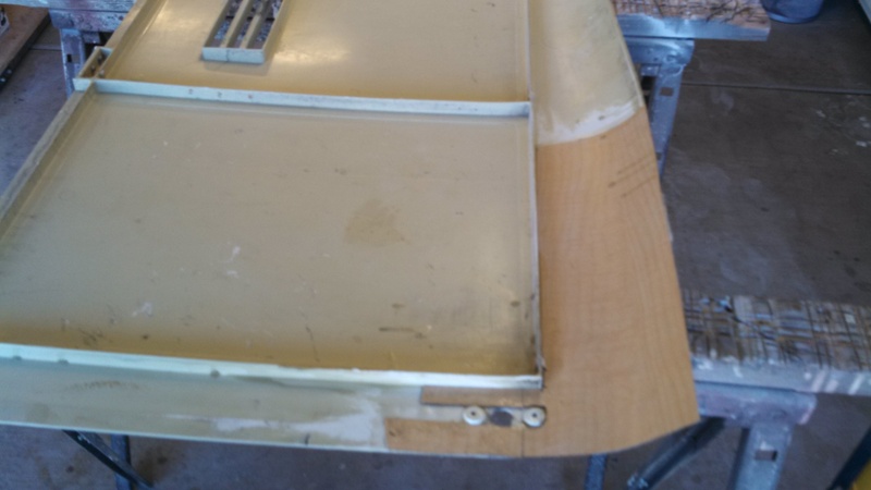
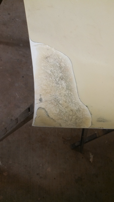
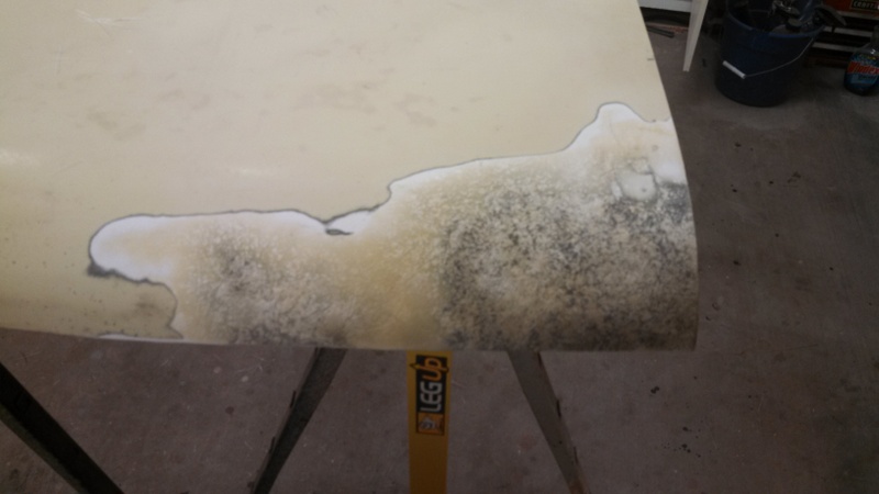
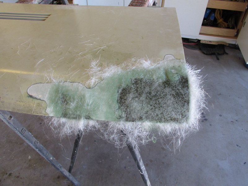
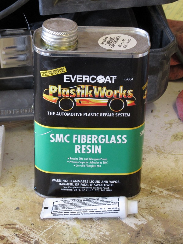
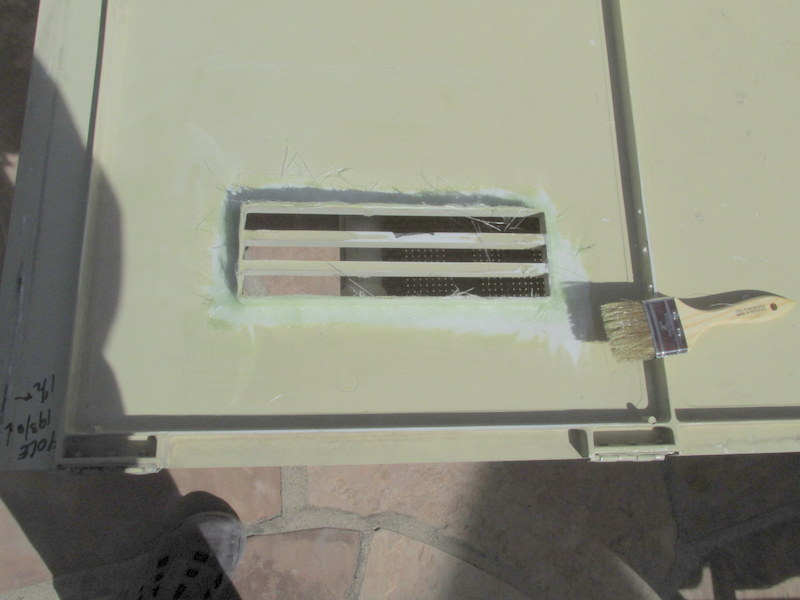
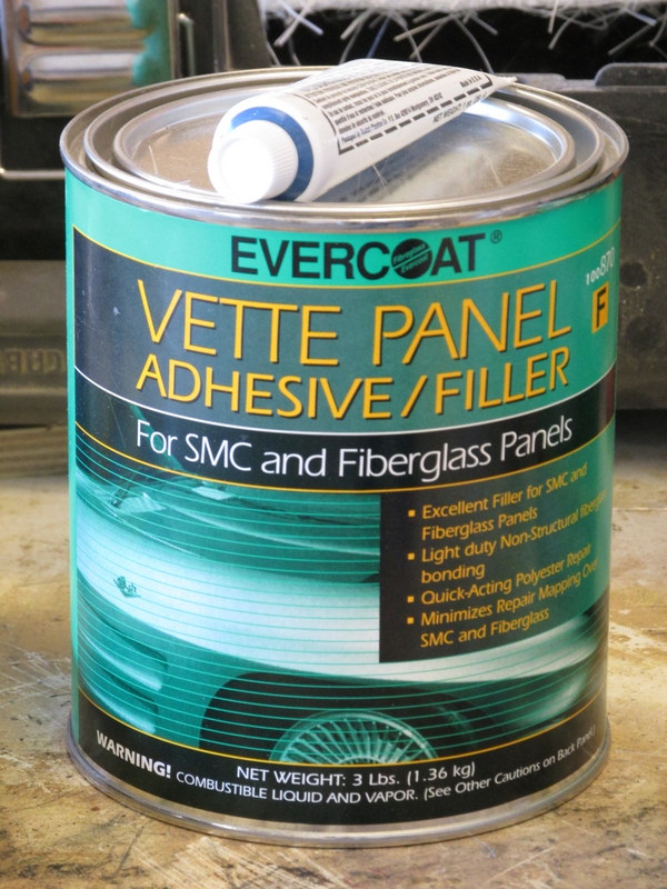
SMC: the end caps and the body below the waist are made from SMC which is pretty much like fiberglass. The SMC panels are glued to the aluminum body structure. SMC contains a mold-release agent that is embedded in the material and must be wiped off with a solvent before repairing. The materials are different than for regular fiberglass and are specifically labeled for use on SMC – and they cost more.
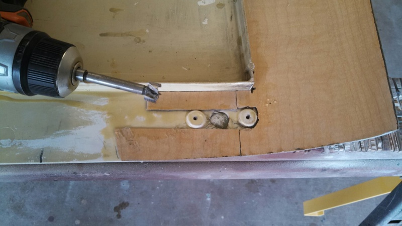
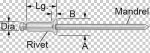 The roof and the sides above the waist are made from 16 gauge aluminum sheet that is glued and/or riveted to an aluminum body structure. Significant aluminum repair requires a lot of skill (that I don’t have) but, fortunately, I only needed to repair a bunch of small screw holes and a couple of antenna holes – about 1” or 2”. Knowing that no one except me and the next owner would ever see the roof close up I didn’t worry about the antenna holes too much. I riveted pieces of aluminum roof flashing under the two larger holes and then covered them with a body filler made for bare metal – you cannot tell (yet). All of the screw holes in the aluminum were countersunk and filled with a countersunk aluminum pop-rivet (McMaster-Carr #97447A210) and then covered with the body filler – quick and easy.
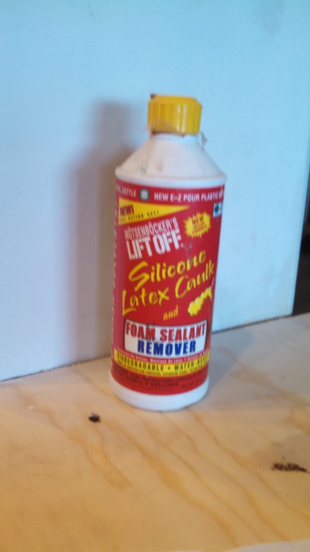
 The only other significant work revolved around removing an accumulation of silicone sealer from a few areas. I used a commercial silicone remover, a putty knife, and a wire brush to get the silicone out of the seams. Nothing sticks to silicone so it has to be removed completely.
Cleaning:
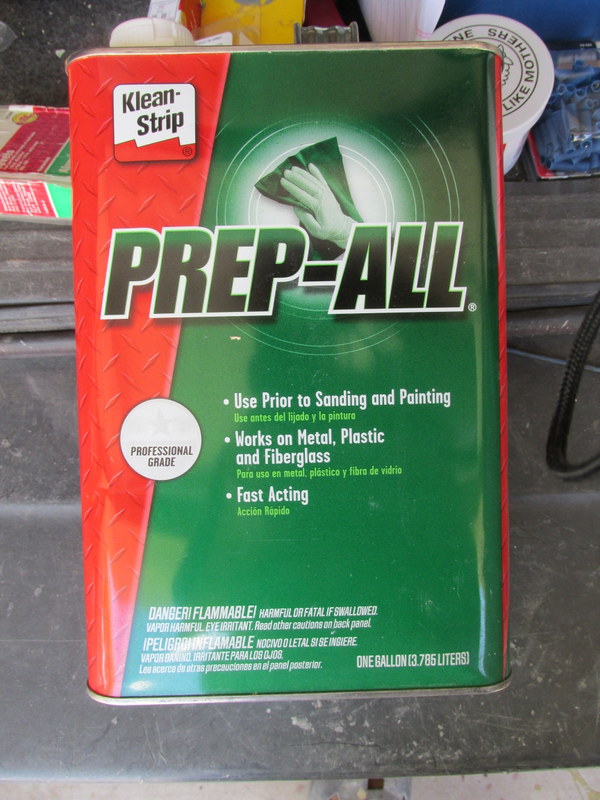
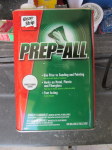 The old surfaces should be cleaned before any more preparation is done. Special attention should be paid to making sure all silicone sealer has been removed before sanding because sanding can spread the silicone. On the heavy silicone deposits on body seams and lots of other places I used Motsenbocker’s silicone remover and I used “Prep-All” from my autobody and paint supplier everywhere – it took off what the silicone remover left.
Masking:
Windows and window frames, bumper brackets and frame, A/C units, and anything else that you cannot get off must be masked. If you are going to mask something and then get it painted quickly you can use cheap tape and paper. If you are going to leave the masking tape on for any length of time (more than a day or two) you should use “good” tape (I used 3M 233+) since it is supposed to be easy to remove without leaving any adhesive behind. If you are painting outdoors then all bets are off. Rain will soften cheap tape and shrink paper. The sun will cause even the good tape to leave adhesive behind after just a day but the good thing is the good tape is very resistant to water.
I masked my coach several times over the course of the project and I found that the best idea was to mask with plastic sheeting (3.5 mil) and “good” tape. This masking can make it through rain and wind with few issues. Since my masking stayed on for several days at a time the tape did leave a lot of residue, particularly on rubber around the windshield and the rear window. Even 3M Adhesive Remover would not touch it but it did come off pretty well with lacquer thinner. Just remember that lacquer thinner removes fresh paint very easily.
Selecting the Paint:
If you were painting a coach indoors in a proper spray booth the whole process could probably be completed in one day – a long day, but still one day. Painting outdoors without the benefit of shelter from the wind and weather changes the picture quite a bit.
One of the things that complicate painting over a multiple-day period is the requirement of some paint “system” components that they be covered by the next component within a certain amount of time. A 2K urethane primer can be applied with no requirement that it be covered within any timeframe but a 2K sealer must be covered the same day. Etch primer must be covered with a primer or sealer within 8 hours. The base-coat (color) of a base-coat/clear-coat system must be covered within 24 hours with either another coat of base-coat or the clear-coat.
I started by trying to understand the choices of paint types: paint products are either “single-stage” or “2K” (two-part) and the state of the art is “base-coat/clear-coat” (BC/CC) systems where the color is applied first and then covered with a coat of clear material that has the shine (or lack of shine). A benefit of the BC/CC system is that drips, sags, and orange peel can be “color-sanded” and then buffed very easily to remove the problem. I was strongly encouraged to use that system so I did not worry about the cost: the total cost for 3 different primers, 2 base coat colors, and clear coat was about $1,000. I did not price the cheaper paint.
The next consideration was color. For the main body we wanted to stay with a light color that was close to the original “cream beige” but was a little more lively. When I went to the local Finish Master store in Tucson I found that picking the color was going to be a little more difficult than I am used to for home decorating colors. Automobile manufacturers invent new colors every year. Each of the new colors is unique and has no complimentary colors – like you would expect for home decorating. If you want a different shade of the same color you are out of luck. Because I was planning to use the Blueocity scheme with only black around the windows I was not worried about more than one color choice but trying to paint 4 different stripes of the original paint scheme with a new set of colors would have been a nightmare.
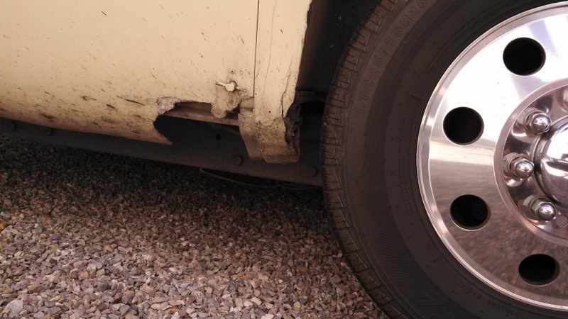
Phase I – Painting the Bottom of Each Side
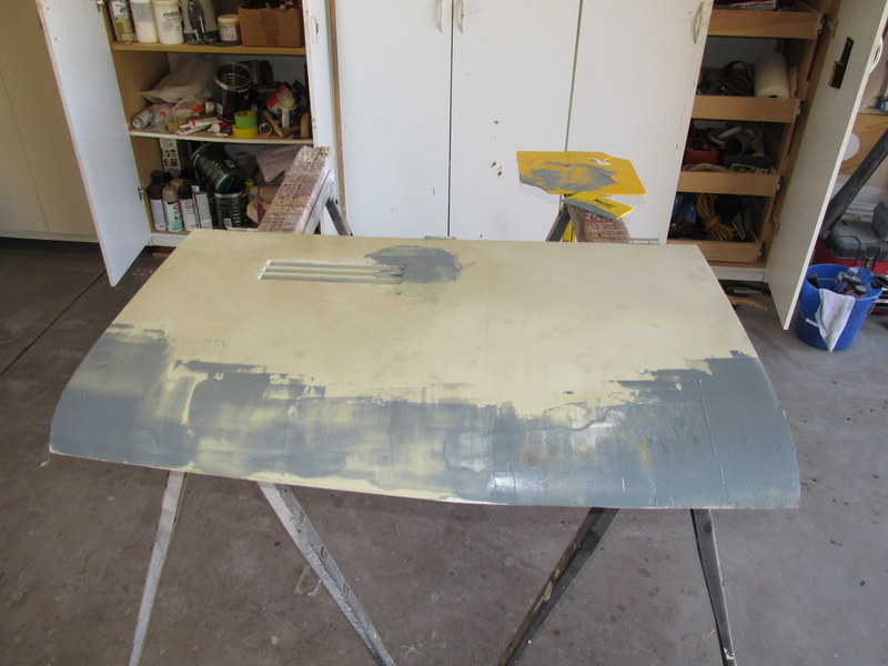
 When I started the project I started with repairing the damage from several tire separations, multiple furnace installations, excessive bolt holes for fender liners and more. I repaired most of the damage and then primed the repairs with a primer that I thought approximated (“close enough”) the color of the original beige paint. My wife did not agree and I was required to get started on the paint job and to not go to the Spring 2014 GMCWS rally unless the primer was covered. The plan was to paint the sides – all of the panels that enclosed wheel wells and everything between them – with the new beige. I planned to paint the aluminum strip that covers the seam between the upper aluminum and lower SMC panels but stop there until after the rally.
I now had to choose a primer – I needed to prime at least the areas that had fresh body work done on them but I was told that the job would look a lot more uniform if I primed the whole thing. I had to use a primer that I could leave uncovered for multiple days because I could only work for 3 or 4 hours at a time and the primer had to be sanded before covering. I was limited to a 2K primer/surfacer –other primers must be fresh when the base coat was applied. The very thick 2K primer did not apply very well with my turbine-driven spray system. I don’t know if a better (more expensive) turbine system would have worked better but I am pretty sure it would have. The problem was orange-peel and it had to be sanded smooth – I got most of it smooth but not all. At least it is uniform 😉
After all of the body work one each of the lower sides was done I applied the primer and then the next few days I sanded out most of the orange peel. I then applied two coats of the (color) base-coat (a little too thin in a spot or two) and then two coats of the clear coat. It mostly came out pretty good although there were areas that needed to be sanded and buffed (this is normal) and one panel that needed to be repainted.
When I was spraying the base coat a dried up blob of paint from the gun stuck to the area right above the passenger side rear wheel well. I didn’t see it until after I had applied the clear coat. When I tried to sand away the bumps from this the next day, I discovered that I had damaged the base coat and that I would have to reapply it to hide the sanding. I “scuffed” and sanded the panel that goes over the rear wheels with everything else between the seams and above the waist line masked. I reapplied the color and then the clear coat. The result was a slightly different color. It turns out that this is common, the color is affected by the temperature and humidity when you are applying the paint.
We went to the rally and hardly anyone noticed the lower sides had been repainted but we did notice that people were much more interested in looking at our coach than they usually are at rallies.
Phase II – Painting the Roof
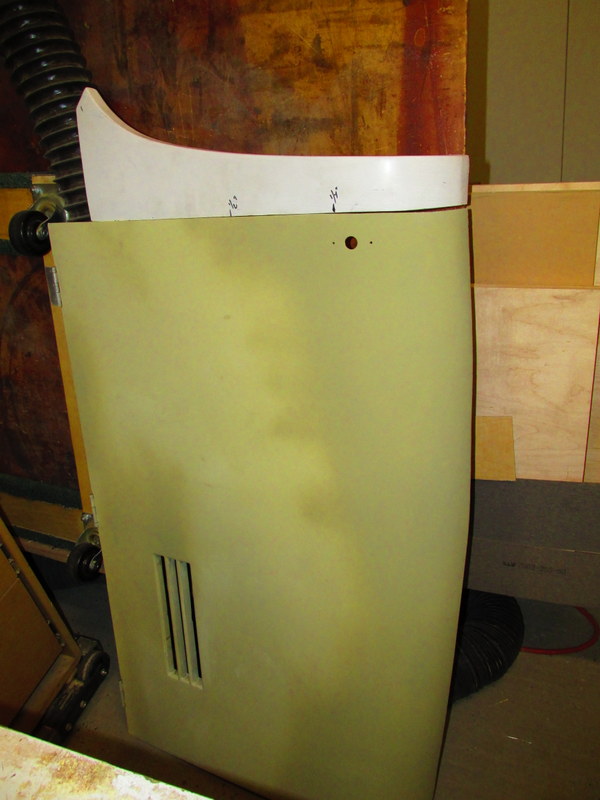
When we returned from the rally it was time to get down to business. The first order of business was the roof – where you sould normally start with a paint job. The roof is made up of three sections: the front cap that covers the cockpit and made of SMC, the main part of the roof made from a single sheet of 16 gauge (I think) aluminum, and the rear cap which is also made of SMC. The front and rear caps were in good shape with only sanding required, the aluminum section of the roof had a lot of small screw holes and their repair resulted in a lot of bare metal on the roof. Bare metal has to be coated with an etching primer and then sealed with a sealer or primer before painting. Also, the etching primer must be covered within 8 hours of application.
I had already figured out that using 2K primer resulted in a lot of extra sanding and I didn’t think that it would be worth the effort to make the roof look good – except on the side where you can see the first foot or so from the ground. Evaluating my alternatives resulted in selection of a 2K sealer rather than a primer to cover the etching primer. The sealer has to be covered on the same day as it is applied meaning the color and the clear coats would have to be applied the same day too. Everything had to be done on the same day. Painting the roof began at 5:00 a.m. with the etching primer. That was covered with two plus coats of 2K sealer, two plus coats of the color base coat, and two plus coats of clear coat. A total of 7 plus coats, all applied from an 8-foot step ladder that leaned on the sides and rear and hardly worked at all on the front cap – too far a reach. I finally finished at around 10:00 a.m. I estimated that I climbed that ladder 3 or 4 steps each time, at least 120 and maybe as many as 160 times that morning.
The roof came out pretty bad with dust, dirt, runs and sags but no one can see it – just me and the next owner.
Phase III – Painting the Rest of the Coach
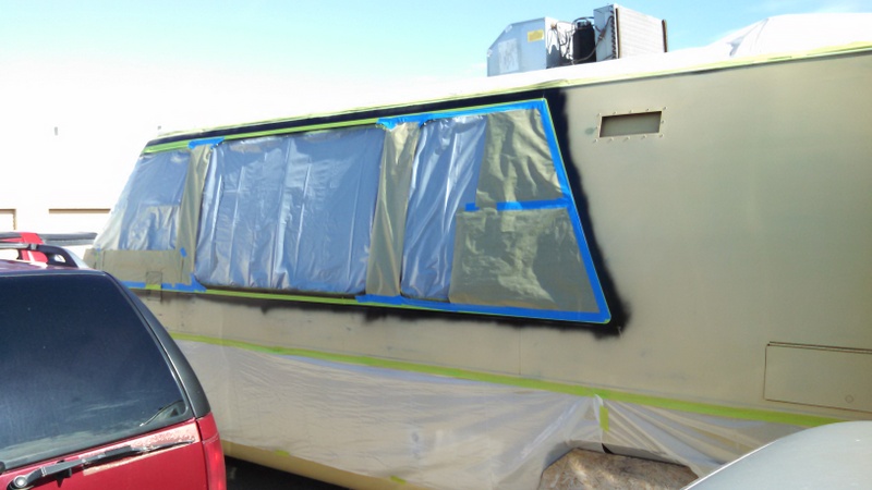
 So far, I had managed to live with the time requirements of the paint system but now I had a problem: painting the rest of the coach involved two colors and that required masking and more work than normal between base coat and clear coat. I could not get the rest of the work done in one day. What remained had to be done in five steps: 1) paint the black around the windows allowing extra paint to make sure everything is covered; 2) mask off the black that I want to keep; 3) paint the beige color; 4) remove the masking over the black; and 5) apply clear coat to the whole area.
Complicating the problem was the masking between color coats. The masking of the black could not be allowed to stay adhered through a hot summer day in Southern Arizona – it would either pull the paint off or leave adhesive behind. In order to get around the sticky tape problem I needed to paint the black in the morning and then mask it in the evening when it was cooler. Applying the second color in the morning and then removing the masking over the black should avoid the tape in the sun issue but what about the requirement to cover the base coat with clear within 24 hours? Applying the clear coat the next day meant that the black would be 48 hours old and the beige would be 24.
The solution is known as “inter-coat clear” and it was really hard to find out about, probably because most shops would do the whole job in a day and not have this problem so almost nobody talked about it. The specification sheets for the base coats say that they can be recoated at any time with another coat of base coat. It turns out that base coat is made up of a clear carrier material with color added. The carrier material is sold as-is and can be applied over previously applied base coats to “refresh” them. Dupont (and their Nason brand) calls theirs “222S Mid-Coat Adhesion Promoter”. Just apply a coat of this acting as if it is another coat of clear-coat and then apply your clear coat. Times between coats of these paints are very short – no more that 15 or 20 minutes.
I applied the black on one morning, then I masked it in the evening, painted the beige the next morning, then applied the clear coat the third morning. The masking did pull some of the black off and I ended up doing repairs: first black, then beige, then black, then beige, etc. for a couple of hours on the second morning before I was happy with the results. I applied the “inter-coat clear” and the clear coat on the third morning.
Color Sanding:
 The great thing about base-coat/clear-coat systems is that they are very forgiving. Orange peel, drips and sags can be sanded out and then buffed to an even better shine than a good clear coat has. The process begins with a very firm or hard sanding block and 1200-grit wet/dry sand paper applied gently the next day. I saw a couple of different techniques on various youtube.com videos but the one that worked best for me was plain water applied generously from a spray bottle to keep the paper lubricated and checking progress by using a rubber squeegee to dry the area quickly so I could see reflected light in it. Once the problem is gone, go over the area with 2000-grit paper and then polish with a buffer and rubbing compound on low speed (you will burn the paint off with too much speed/heat). The biggest problem is residue of the compound in adjacent seams.
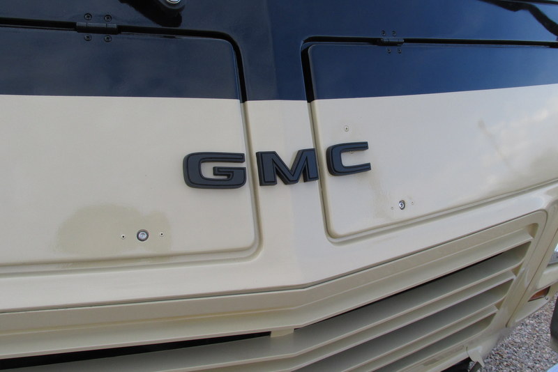
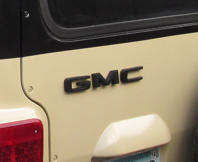
Plastic GMC logos:
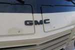
 I wanted the coach logo badges to be as close to original as possible so I made new ones. I made molds from the original logos, cast exact replicas of them, and then painted them black and clear coated them.
 
Summary:
I am glad that I did it but I would not do it again without a proper place to work – at least an enclosed area. I estimate that I spent a total of 200 to 300 hours and, counting all materials, supplies, nuts and bolts, trim, etc. about $2,500. I could have probably saved a few hundred on cheaper paint materials and I already had the sprayer, sanders, grinder and polisher.
It would have been a lot harder without Jim Bounds’ help and advice.
I started out looking for a “10-foot” paint job, I probably have about a “5-foot” paint job and that is what I would probably expect from a local body shop for a minimum of about $5,000. I think that a cheap “bag and shoot” paint job probably suffers from more than visible preparation problems and will probably have some adhesion issues before too long.
I think a quality paint job – good preparation and expensive materials – will cost somewhere upwards of $10,000 with minimum body work required. Add more for repairs, trim, and various nuts and bolts and you are up to at least $12,000. I would expect that paint job to be at least a “5-footer” though.
Below is the slide presentation of this write-up that I did for the GMCWS rally in October 2014:
http://minniebiz.com/gmcmotorhome/wp-content/uploads/2014/11/Painting-My-GMC.pdf
 Share on Facebook

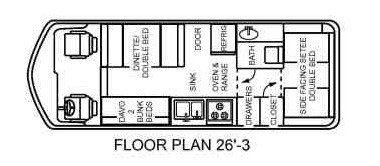 When we bought the GMC, a 1976 Eleganza II, it was a pretty vanilla version of a GMC Motorhome. We used it that way for about the first 4 years of ownership. About 7 years ago, in 2010, we removed the side-facing setees and converted the back section into a permanent bed. We also removed the dinette that converted into a double bed and replaced it with a couple of Honda Odyssey middle bucket seats and a round table. The davo on the driver’s side that converted into a bunk bed was removed in favor of a sofa that I made from wood with two large and very useful drawers under it.
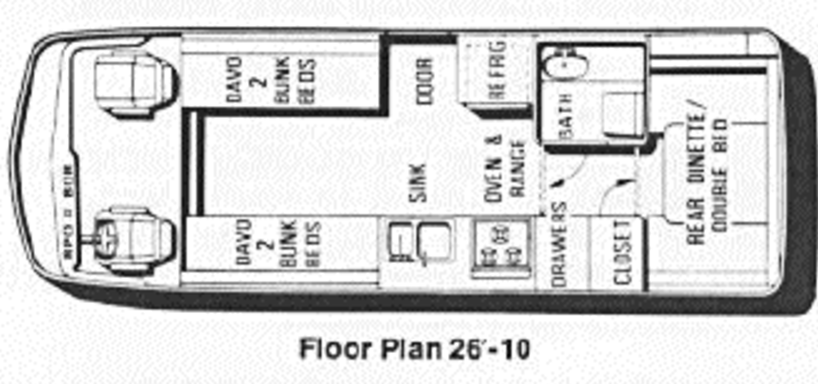 With twin beds becoming an alternative we took another look at the GMC and saw some new possibilities. Carol, from day 1, loved the idea of a dinette in the back where the permanent bed now was. When we bought the coach the side-facing setees were set up and looked very inviting with that giant rear window. There was no table back there and I doubt it ever had one but we could imagine it. We decided to remove the permanent bed to install our own version of a rear dinette and to remove the bucket-seat dinette (which we had come to dislike a little anyway) and replace it with a mirror-image couch like the one I had been sleeping on. With both couch/beds open for sleeping there would be about 14 inches of space between them – plenty of space to allow getting in and out of bed during the night without disturbing each other. The benefit of using the areas in front of the entry door and the kitchen for the twin beds is that there is more room for slightly longer beds