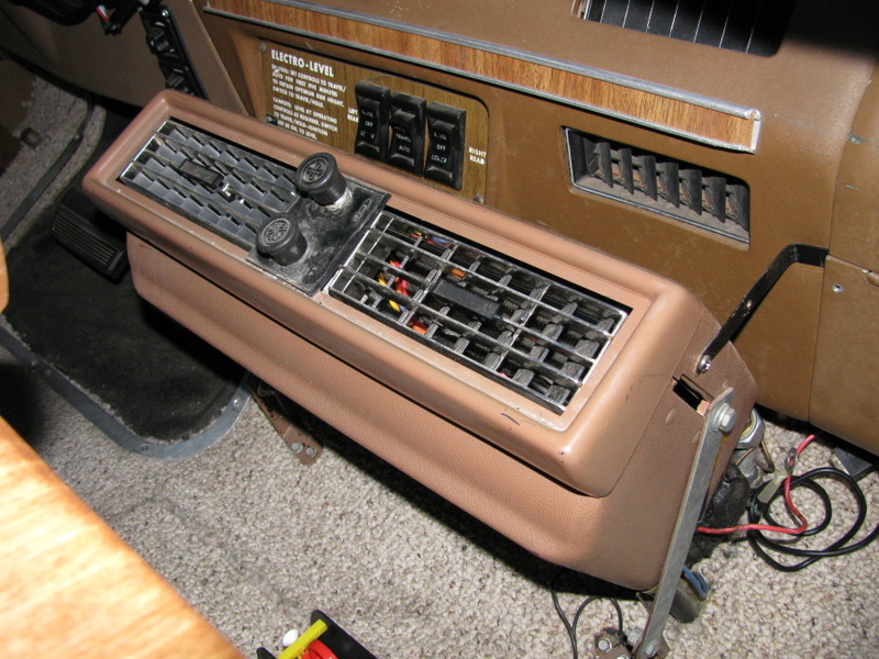
Under-dash air conditioner installed by a PO.
When we got our coach it had an under-dash air conditioner that some previous owner (PO) had installed in place of the original equipment (OEM) setup. The OEM system was never very good until the mid-1977 and 1978 models and even then I hear complaints. Our coach is a 1976 so the system was not good – it did not blow very much air and what it did blow was 100% from outside air so it was not very cool and gave hardly any heat in the winter.
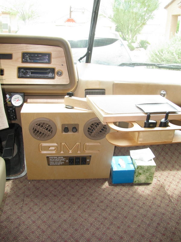
My solution to the ugliness and inconvenience of the PO-installed under dash unit
The under-dash unit was in the way, poorly installed, and made lots of noise from fans hitting housings, etc. I hated the way it looked and hated that it got in the way of the suspension switchs and of having a tray or other platform for holding drinks, food, and our navigation computer. A couple of years ago I made a cover for the under dash unit that made it a lot more attractive and incorporated a swiveling tray that held drinks, food and our computer.
Our last trip – the June 2015 trip to Northern California – was so hot and uncomfortable that I decided to do something about it before our next trip in September when it will still be hot here. I had read and heard that there were solutions to the problems with the OEM system. One fellow GMCer that I talked to last Spring at our Treasure Island rally said that he had to turn his down on the trip to the rally even though it was about 100 degrees out.
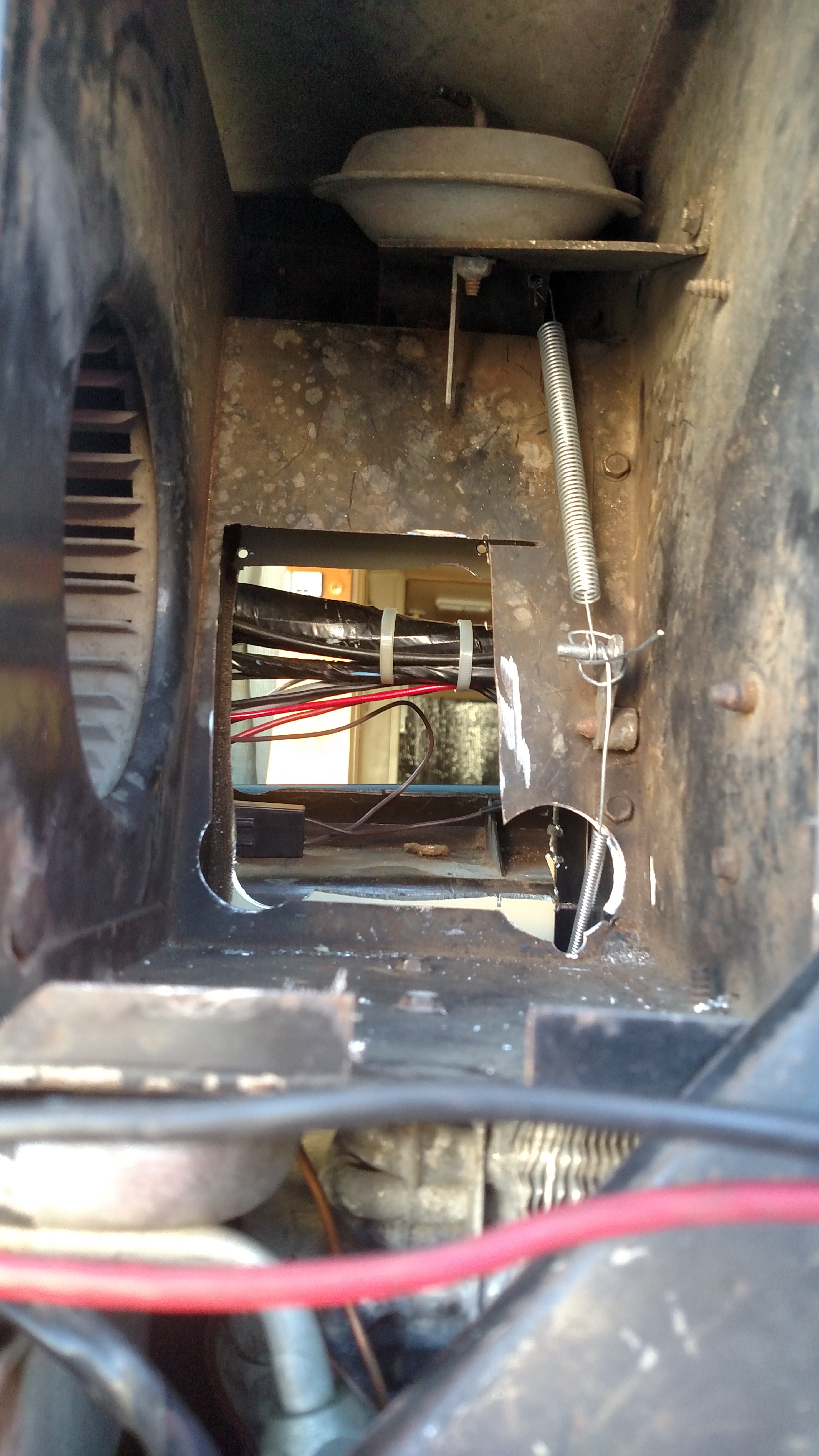
This is showing the hole that I cut in the back of the input chamber of the HVAC box and the coach fire wall to allow inside air to be taken in instead of the hot outside air as designed. The damper control on the right is the “max air” damper that is now normally open unless the “defroster” cable is pulled. The spring helps keep it open.
Fixing the OEM system requires two things: converting the system so that all of the input air is recirculated from the already cooled (or heated) interior air – commonly called “recirculate” on controls. This involves cutting a hole in the back of the fan intake section of the system and through the firewall so inside air will be drawn in. Covering the outside air intake forces all (95% probably) air to come from inside the coach. The OEM control has a position on the temperature control that says “recirc” but it does not – that control is supposed to open a door that sends most of the cooled air inside so should be labeled “max air” if anything. There is no recirculation in the original setup.
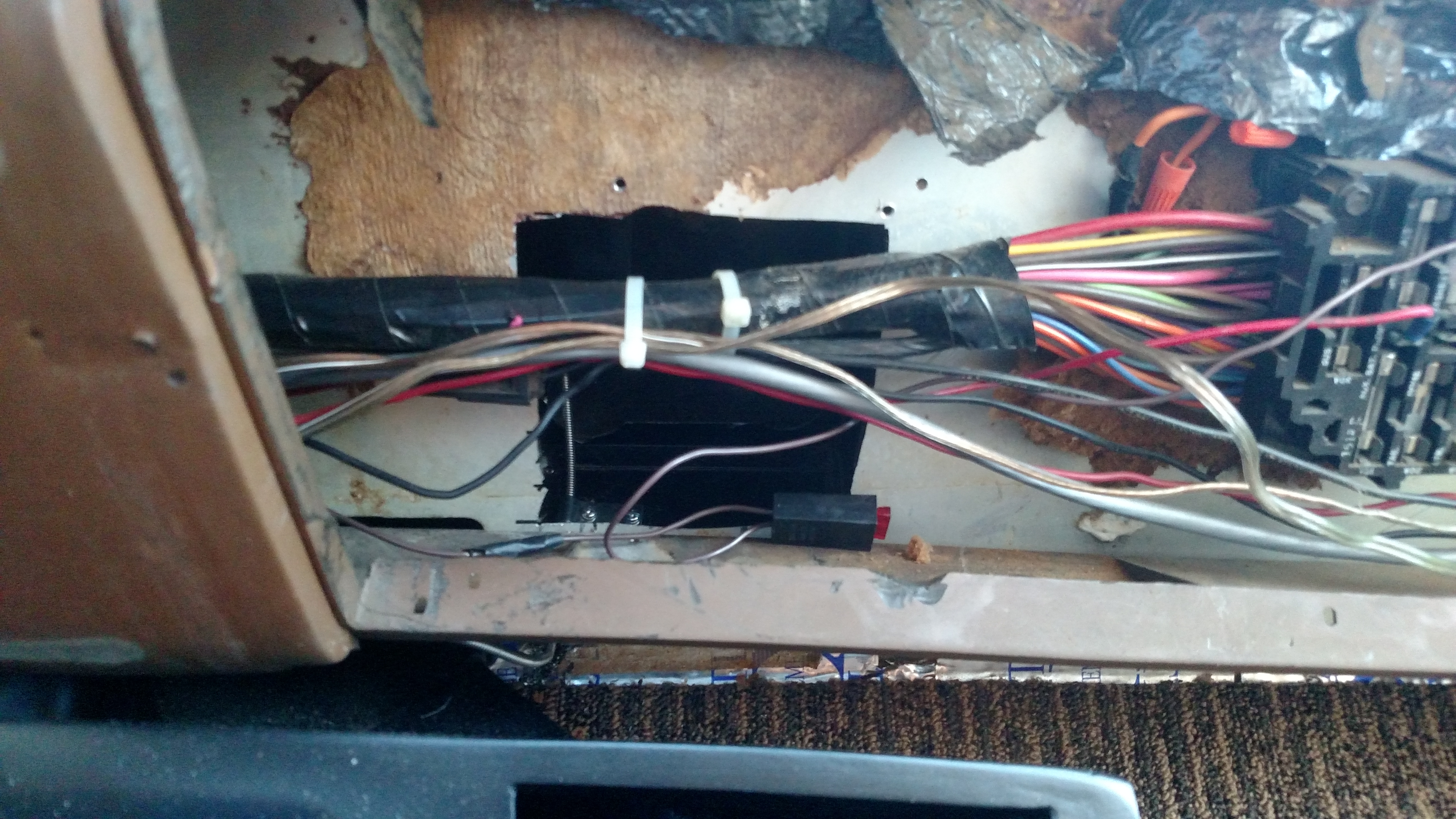
This is a view of the hole in the fire wall from inside the coach. I used a hole saw, a 4 1/2″ grinder, and a reciprocating saw to make the hole. I protected the wires with blocks of wood while I was cutting. This hole is directly behind the glove box and next to the fuse box.
The second part of the requirement is to simplify the routing of the conditioned air – the standard ducting system is so convoluted that hardly any air comes out. I looked at our system and determined that the duct work and its controls were so old and leaky (it uses vacuum from the engine) that it was hopeless to get it working again. One of the vacuum actuators actually disintegrated in my hand when I touched it. Instead of using the ducting system I plan to just keep the “max air” door open all the time unless we need defrosters at which time I will close the “max air” door and allow air to go through the OEM ductwork but completely uncontrolled. I also plan to turn the heater valve on and off mechanically (instead of the non-functional vacuum system) and control the flap that regulates the amount of air flow over the heater core mechanically (like it was originally). The heater valve, the “max air” door, and the heater air flow damper will all be controlled using old-fashioned manual choke cables in place of the non-functioning vacuum actuators. The air conditioner will be turned on with a toggle switch and the fan will be controlled using the OEM switch and wiring.
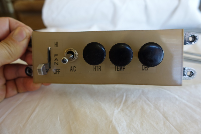
The modified OEM control panel has the original fan speed switch on the left with 4 controls on the right. The toggle switch controls the air conditioner clutch and when it is lit on the end. The first knob turns the heater valve on and off, the second controls the heat damper, and the third closes the max air vent damper and forces the air through the duct work and maybe some defrosting.
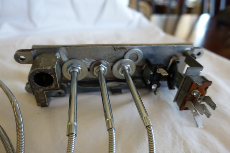
The back side of the OEM metal control panel – the extra washer is because there was a high spot on the other side of that control that needed to be offset
Since I needed to hold the original fan speed switch, a toggle switch for the air conditioner, and three “choke” cables I decided to just modify the OEM control panel. The front of the control panel is made of cast metal with a plexiglass insert. The back of it has standoffs to hold the fan speed switch. I removed the plexiglass insert and used a grinder to flatten out the face of the metal part so that I could replace their plexiglass insert with my own. In the original arrangement of controls the right side of the panel had two left-to-right slide levers that selected mode and temperature. I drilled holes in the slot that housed the top slider and backed them with washers to hold the new controls. I made my insert from a 1/8″ plexiglass scrap, printed clear labels with mirror imaged text that I installed behind the plexiglass and then painted the back of the plexiglass to hide the ground-down metal panel behind it.
The cable that controls the heater on/off valve and the one that controls the damper that controls air flow over the heater core were no problem but the “defroster” cable, the one on the right, is a problem. My idea was that under normal conditions the “max cool” opening under the dash would be wide open and when we needed the defroster function I could close that damper and force the air through the old vent system and then some of it would be directed on the windshield. I had a real hard time getting the cable positioned correctly to perform the function because of the position of the control lever and the directions it had to move in.
Below are some detail photos and the finished product. I can report that the dash air conditioning is now performing the way you would expect a good dash-air system to work – it blows lots of cold air. Success!
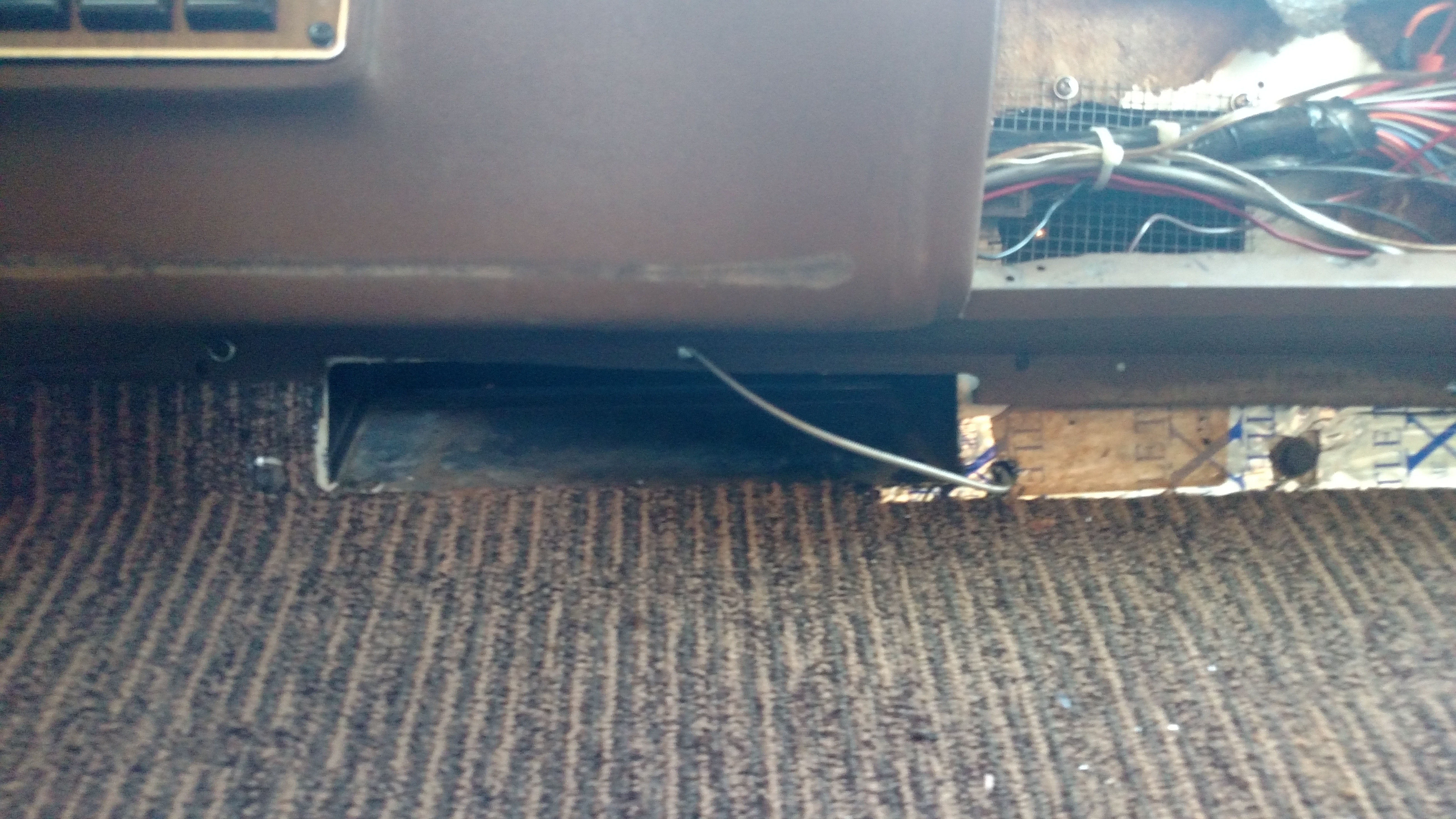
The “max air” vent exits the HVAC box in this approximately 2″ x 12″ hole under the dash and pretty close to the new intake hole. The damper that is supposed to open with “max air” is right beyond this hole. Originally, there was duct work that directed this air toward each side of the cockpit. The cable that is crossing the opening is the “defroster” control cable making its way from the dash panel to the HVAC box – it was slightly repositioned later to avoid conflict with the duct work.
This shows the duct work that I got from Golby in Florida in place and waiting for the diffusers that Golby also supplied. The wooden piece attached to the dash is the console pivot point holder.
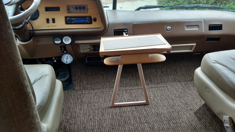
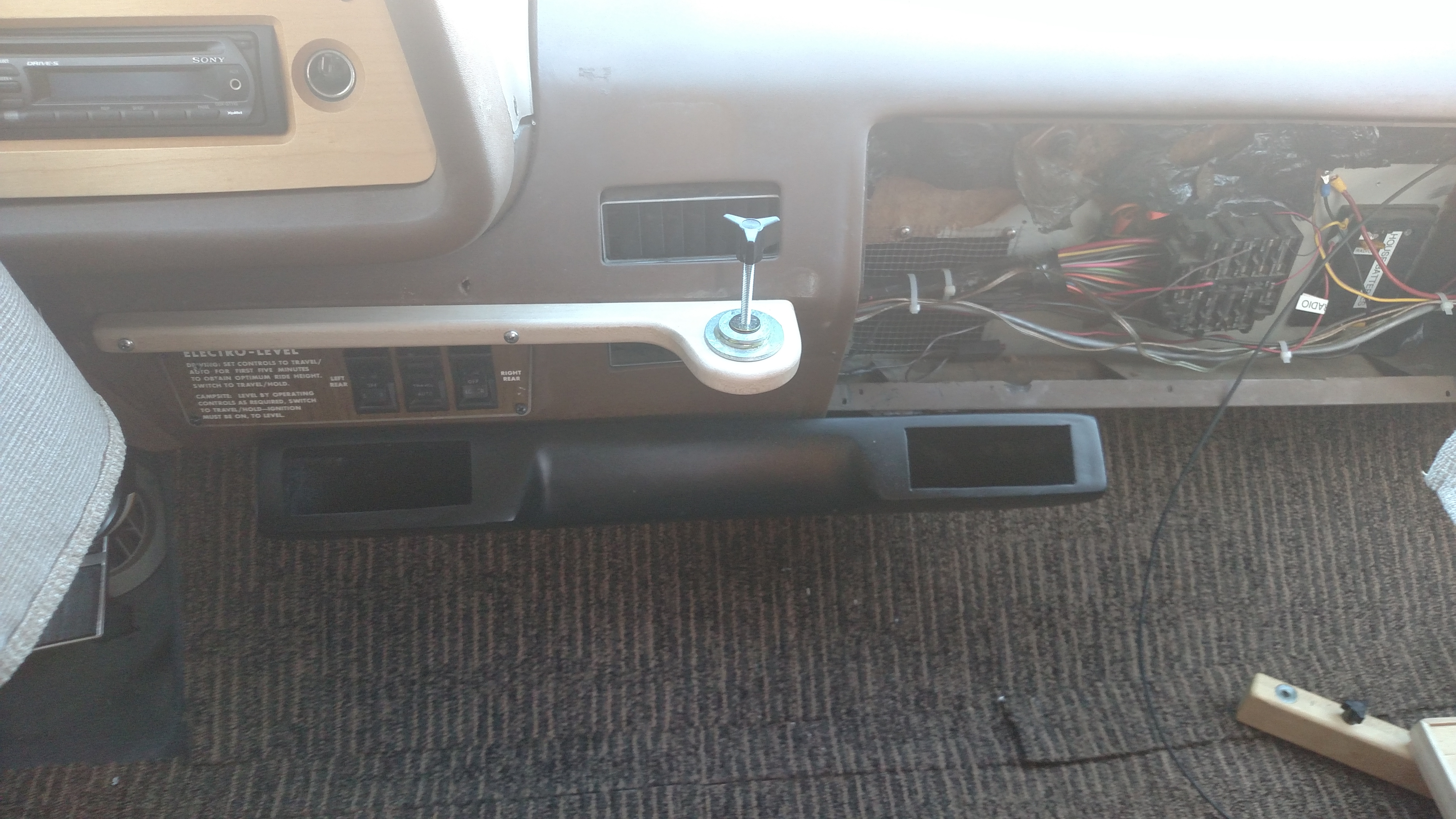
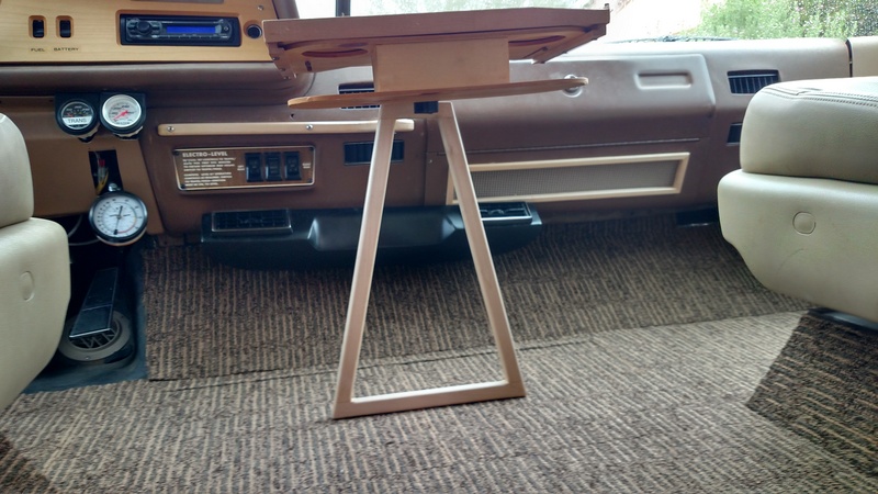
This is the new center console arrangement. The triangular gizmo holds it up and provides side-to-side stability while allowing it to be positioned where we want it. Moving it just involves lifting and sliding side to side. Removing and storing it is easy too.
This view shows the “finished” product. I cut a hole in the glove box to allow the return air to flow more easily. I installed the diffusers in the max air duct and they really help direct and focus the cold(!) air.
No Comments Yet